31.01.2022 -- #
After months of work I’m pleased to announce I installed my DIY reef controller today!
Yesterday:
Today:
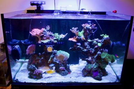
The Сева (Sewa) Controller replaces a rats nets of outlet timers and manual processes with a micro-controller plus relay power system. It brings a more complex flow simulation, automated feed mode, and refugium light schedule to my 300 liter reef aquarium.
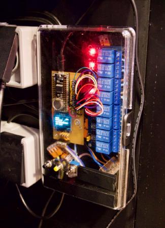
sump power wall
Designed after my i300C Dive Computer the user interface consists primarily of two buttons. One button advances modes and the other activates the mode. Beside that is an override switch. The available modes are:
- Feed: When activated all pumps turn off for five minuets, allowing time for the fish to eat. Then the two circulation pumps activate for five minuets, allowing the coral catch food or absorb amino acids when I dose those. After ten minuets total the main pump comes back on line and filtration resumes.
- Outlet ID: This turns everything off and allows you to step through outlets one at a time to identify them. This way its easy to ensure the correct pumps are plugged into the correct outlets.
- Power Statuses: A simple read out of which things are on, for debugging purposes.
- Reset: Puts pins back to default allowing for simulation to resume.
xl300
As water swooshes between the crevices of the rockscape and around the tank it does a number of important biological processes:
- It brings nutrients to and from the coral.
- Provides fish with resistance to swim against.
- Brings water into contact with nitrifying filtering bacteria on and in the rock.
Besides modes the controller does simulation / scheduling in the background to enable more varied water flow. Previously I had both circulation pumps on a timer where they were on for two and a half hours then off a half hour. Building off that idea with the controller I broke every three hours into 30 min chunks, then applied a one of the following flow patterns:
- Flow to the right
- Flow to the left
- Mixing flow, both pumps on
- Calm, both pumps off
It’s very fulfilling to sit next to the tank in home-office and hear it every 30min change flow patterns.
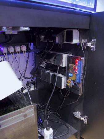
sump
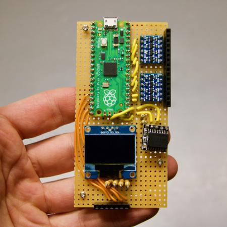
On the hardware side the controller is made up of the following parts, starting from top left and going down:
- Raspberry Pi Pico, this is the brains of the system. I went with the Pico because of its cost and ease of programming with CircuitPython. I also looked at ESP32 boards but decided the consequences of a system failure being very expensive coral and fish dying adding WIFI was a unsafe complication to the system.
- Two shift registers to allow the 3v logic of the micro controller to interface with the 5v logic of the relay board.
- Two female pin headers to allow for removable connection between the board <-> cover with inputs and between board <-> relay board.
- I2C LCD display.
- RTC (real time clock), similar to the what you would find on a computer motherboard this keeps time even when power is out. I started off with a small DS3231 but ran into problems so I swapped it for a Adafruit DS3231 Featheer board.
- Relay board, standard 8 channel relay board. This allows the three volt logic micro-controller to control full 220 voltage pumps and lights.
- Interface panel comprised of two push buttons and a three way switch.
- Case is up-cycled from a soldering iron case.
Bring these parts together was a process of trial and error. Sometimes setting it down in frustration for weeks. Originally I wanted to have 10 controlled outlets with individual override switches for each. A grand plan, but it was simply to much to pull off and I had to tape over the extra holes in the case. In the end I reduced the inputs and limited the number of controlled outlets to eight. Of the eight I’m only using four at the moment.
board, pre rtc swap
The program I wrote for the micro-controller is available on sourcehut. It is entirely in CircuitPython so development is straightforward and much easier for me then C++. I designed the logic around a simple publisher subscriber event system. Example:
A timer fires every 15 seconds triggering the RTC module to read the current time from the RTC chip. The current time is then published and a verity of other modules make calculations. The flow simulation module takes this time and determines which of the flow patterns should be running and publishes messages to turn on/off the needed pumps. The power module gets this requests to turn on a pump, checking priority to ensure things like feed mode are not interrupted, and then supplies power to the correct pin which then gets logic shifted to 5v and the relay board magnetizes a corresponding relay and power flow to the pump.
When real world things happen in responce to this programmed event system it super exciting! Another example is pressing the adv button twice followed by sel button once:
Input events are published and the mode module navigates the mode tree, in this case to the feed mode. As modes change the various other modules take responsibility and publish rendering events with text. The rendering events are processed by the display module who actually takes care of the I2C communication to the LCD. Pressing the sel button in this cases counts as a ‘click’ on feed mode, so the feed mode module activates and sends messages to turn off all pumps and starts a timer to turn them back on after five/ten minuets.
This might sound complex but now that it is installed everything happens as it should without the need to remember much. Just having the pumps turn back on after feed mode could have saved my corals a stressful time that had last week when I forgot the circulation pumps for 12 hours.
Next steps
Enough sitting back and enjoying the controller do it’s work, time to plan next steps. I’ve ordered two more circulation pumps and when they arrive will program them to achieve circular flow patterns. In total I’ve four more controlled outlets to fill. Come summer I’m planning on adding a T5 bulb light which will become part of the system. Also time to start on a separate internet connected sensor project for the tank. Look forward to more hobby-electronics + reef aquarium posts.
Tips
This project has been a steep learning curve for me. I hope other can learn from it.
- Start small, my original to have individual switches for every outlet was a nightmare to wire. Two buttons and a switch can go a surprisingly long way if you are creative with them.
- Stop and test often. When I first started the project I would work for days without testing what I made. Then one hidden falsely soldered joint would give me another few days of headace. These are easier to find if you’ve only soldered a few things since you last tested.
- Using female headers to make parts removable is super nice. It worked great for the front panel and I think I’ll upgrade the relay board connection to be more similar.
- Working with 220v is no joke. Respect the danger and don’t open the box unless everything is unplugged.