06.07.2021 -- #
We have mood lights in the bedroom that are hard to enjoy. Every day we must remember to plug them in and every night lean far out of bed to turn them off, not optimal. Adding a timer into the mix helped by automatically turning the lights on at a set time but had downsides: still had to unplug the lights to turn them off, had to remember to plug them back in come morning, and timing would become out of sync with sunset time. On a quiet weekend Masha and I decided to build a light controller.
Enter project Bedroom Light Controller, a DIY solution to your lighting woes! Lights synced with the sunset, turning on automatically. If not disturbed the lights will turn off at 3am, however if you should want to go to bed earlier simply tap the button and enjoy your dreams.
Build log
The controller follows a simple design with four main components: a micro-controller to handle logic, a real-time-clock, a button for input, and a relay to switch the outlet on. All these components reside in a box that has two wires coming from it, one plugs into an outlet the other is an outlet for the lights to be plugged into. Power flows from the wall to the box then the micro-controller decides if it should let power through to the outlet line.
I chose the new raspberrypi pico micro-controller for this project do to it’s impressive feature set and current hype. I am quite happy with the board. There is no WIFI capabilities which in this case is welcome to keep things simple. First challenge with the board was figuring out how to power it.
Most tutorials online use USB for power, as in a USB wall wart / power supply + USB cable to convert the house 220v AC power down to 5v DC. For this project I wanted everything to fit into a small box and only use one wall outlet, so that would work. Instead we decided to extract the transformer board out of a wall wart and use that in the box.
dremeling into the powersupply
To get it out we used my new rotary / dremel tool. The tool rapidly spins a sandpaper disk melting its way through the plastic housing. Hardware Hacking!
guts

case removed
Once we had the transformer board out of the case we desoldered beefy plug pins and moved on to prototyping, starting with the RTC (real-time-clock).
In this project the micro-controller will be making decisions based on what time it is, but by default the controller does keep time. This is what RTCs solve. Using a special oscillator crystal and temperature sensor an RTC chip can accurately track time. I went with the DS3231 because of its extreme accurately and <4 EUR price tag. Because it sits on a separate chip from the pico it must communicate over wires. This RTC uses the I2C protocol comprising of four wires: RED 3.3v power, BLACK ground, Yellow Clock, Yellow Data. I found the protocol fascinating, and you can learn more about it here.
Once the RTC was plugged in we wrote a script to set the time. Now the pico knew what time it was and would be abled to compare that with sunset times it stored in flash memory. I got those times via this script which uses handy open source suntime library.
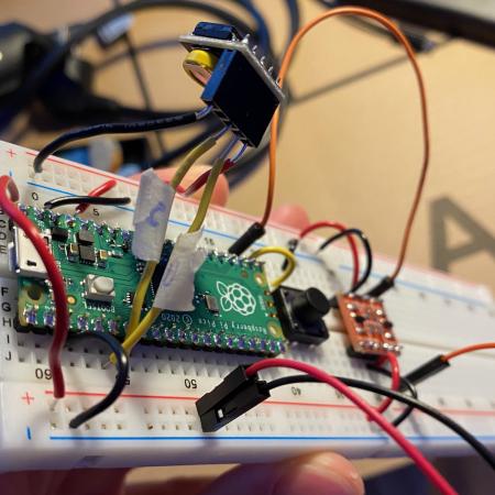
breadboard prototype
Next to figure out was the relay. This tricky part combines many different voltage requirements. It switches the house power of 220v, the board itself needs to be powered at 5v, and the signal to flip the switch comes from 3.3v logic of the micro-controller. To accomplish this I fed the relay board 5v DC from the AD-DC transformer then used a logic lvl converter chip to convert the 3.3v signal from the pico to 5v. All this in place I was surprised it worked on the first try. Luckily it did and all that was left was a simple button.
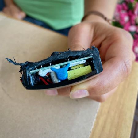
With everything tested on the breadboard I moved on two soldering things to a pico perf board and trying to fit them in the case. 220v is dangerous so I did my best to separate the high voltage contacts from the low voltage ones, using plenty of hot glue to make sure the cables can’t be pulled out. In the end it came together smoothly.
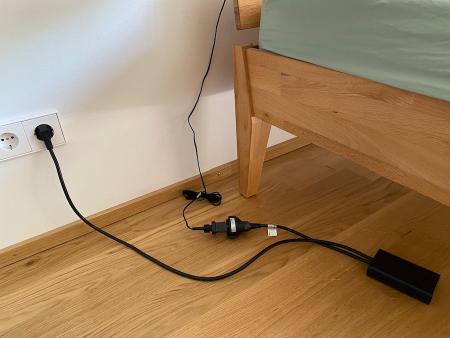
deployed in the wild
That covers the hardware but how does the software work? This project was my first to use circuit python. After only a couple hours I already love it more then Arduino and C++. It is so much easier to use and will open this hobby to less programmer focused people. Now on to what I wrote.
The main script that runs on the pico can be found here. There is a loop that runs every 10ms checking if the button as been pressed, handle_btn_press, and a function that runs every 30 sec, update_to_scheduled_status, to check if it’s between sunset and 3am and turns lights on accordingly. When the button is pressed the lights are toggled and that update 30 sec is bumped back 8 hours.

closed box
In practice this means the lights come up with sunset then when we are ready for bed the button is pressed and they turn off for 8 hours. After that the update function resumes running every 30 sec but by then its past 3:00h so it keeps the lights off until the next sunset.

open box
Such a fun project! Also was great to get Masha into hobby electronics. Expect to see more home automation projects in the future, automating my aquarium devices and adding monitoring to my tank might be next.
repo: https://git.sr.ht/~travisshears/bedroom-lights-controller
Update 08.07.2020
Added data logging to when the button is pressed. Masha had the idea of analyzing this data in some months.